【学习笔记】Windows GDI绘图(五)图形路径GraphicsPath详解(上)
文章目录
- 图形路径GraphicsPath
- 填充模式FillMode
- 构造函数
- GraphicsPath()
- GraphicsPath(FillMode)
- GraphicsPath(Point[],Byte[])和GraphicsPath(PointF[], Byte[])
- GraphicsPath(Point[], Byte[], FillMode)和GraphicsPath(PointF[], Byte[], FillMode)
- PathPointType
- 属性
- FillMode
- PathData
- PathPoints、PathTypes
- PointCount
- 方法
- AddArc添加椭圆弧
- AddBezier添加贝赛尔曲线
- AddClosedCurve添加封闭基数样条曲线
- AddCurve添加基数样条曲线(开放)
- AddEllipse添加椭圆
- AddLine添加线段
图形路径GraphicsPath
定义:表示一系列相连的线段和曲线。
namespace System.Drawing.Drawing2D;public sealed unsafe class GraphicsPath : MarshalByRefObject, ICloneable, IDisposable
应用程序使用路径绘制形状的轮廓、填充内部和创建剪裁区域(clipping regions)。
图形引擎在世界坐标空间中维护路径中几何形状的坐标。
一个路径可以由任意数量的图形(子路径)组成。每个图形由一系列连接的线段和曲线组成,或由一个几何形状基本体组成。
一个由一系列连接的线段和曲线组成的图形(起点和终点可能合重合)是一个开放的图形,除非它被显式定义为封闭图形。可以使用CloseFigure方法显示地封闭一个图形,该方法通过从终点到起点连接一条线来封闭当前图形。
由几何形状基本体组成的图形是一个封闭的图形。
为了填充和剪切,所有开放图形都会通过在力的起点和终点之间添加一条线来封闭。
当创建路径或封闭图形时,会隐藏地启动一个新图形。当调用StartFigure方法时,会显式地创建一个新图形。
当将几何形状基本体添加到路径时,它会添加一个包含该几何形状的图形,并隐式地启动一个新图形。因此,路径中总是存在一个当前图形,当将线段和曲线添加到路径时,会根据需要隐式地添加一条线,以连接当前图形的终点与新线段或曲线的起点,从而形成一系列连接的线段和曲线。
图形具有描述如何从起点到终点之间的线段与曲线的方向。该方向由线段和曲线添加的顺序或由几何体形状基本体定义。方向用于确定剪裁和填充路径的内部。
全文图像
填充模式FillMode
解释GraphicsPath前,先说明下路径的两种填充方式 Alternate交替模式 和 Winding绕线模式
这两种填充模式都使用奇偶规则来确定如何填充封闭路径。
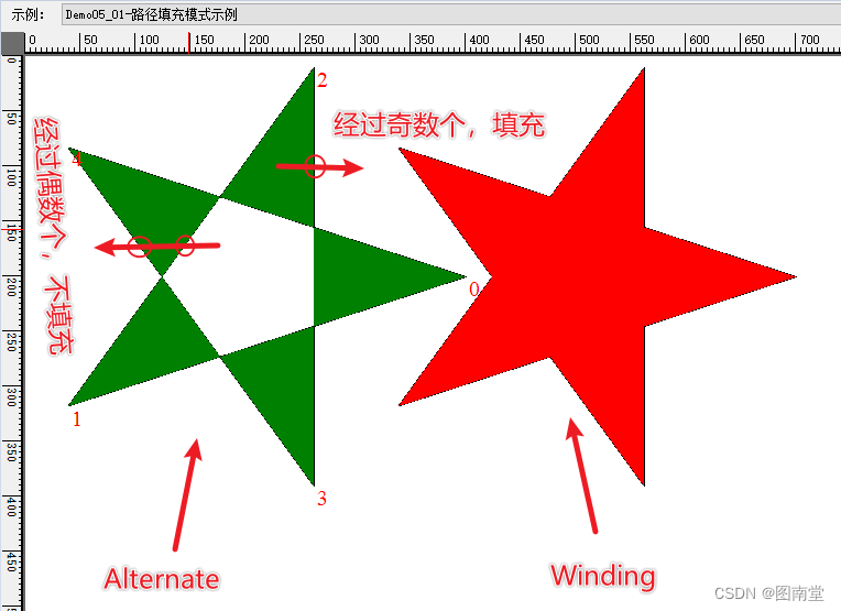
Allternate:
- 从你感兴趣的点画一条射线(通常是水平线)。
- 数一下射线与路径的边相交的次数。
- 如果交点数是奇数,点在路径内部;如果是偶数,点在路径外部。
Winding:
- 从你感兴趣的点画一条射线(通常是水平线)。
- 对射线与路径的每一个相交点,根据相交时路径边界的方向(顺时针或逆时针)进行计数:
- 如果边界从下到上穿过射线,加1。
- 如果边界从上到下穿过射线,减1。
- 如果最终计数结果不是0,则该点在路径内部;如果是0,则该点在路径外部。
[System.ComponentModel.Description("路径填充模式示例")]
public void Demo05_01(PaintEventArgs e)
{//生成五角星的顶点var pts = CalculateStarPoints(200, 200, 200, 5);//默认填充方式:Alternateusing (var path = new GraphicsPath()){path.AddLines(pts);path.CloseFigure();e.Graphics.DrawPath(Pens.Black, path);e.Graphics.FillPath(Brushes.Green, path);//标志顶点顺序using (var font = new Font("Times New Roman", 15)){for (int i = 0; i < pts.Length; i++){e.Graphics.DrawString(i.ToString(), font, Brushes.Red, pts[i]);}}//修改填充方式path.FillMode = FillMode.Winding;using (var matrix = new Matrix()){matrix.Translate(300, 0);path.Transform(matrix);e.Graphics.DrawPath(Pens.Black, path);e.Graphics.FillPath(Brushes.Red, path);}}
}
构造函数
GraphicsPath()
原型:
public GraphicsPath ();//默认FillMode为Alternate
构造一个填充方式为Alternate的GraphicsPath实例。
GraphicsPath(FillMode)
原型:
public GraphicsPath (System.Drawing.Drawing2D.FillMode fillMode);
构造一个指定填充方式的GraphicsPath实例。
GraphicsPath(Point[],Byte[])和GraphicsPath(PointF[], Byte[])
原型:
public GraphicsPath (System.Drawing.Point[] pts, byte[] types);
public GraphicsPath (System.Drawing.PointF[] pts, byte[] types);
通过指定点集和点集路径类型生成GraphicsPath实例,填充方式为Alternate
GraphicsPath(Point[], Byte[], FillMode)和GraphicsPath(PointF[], Byte[], FillMode)
原型:
public GraphicsPath (System.Drawing.Point[] pts, byte[] types, System.Drawing.Drawing2D.FillMode fillMode);
public GraphicsPath (System.Drawing.PointF[] pts, byte[] types, System.Drawing.Drawing2D.FillMode fillMode);
通过指定点集和点集路径类型生成GraphicsPath实例,并可指定填充方式
//定义点集
var pts = new PointF[]
{new PointF(100,100),new PointF(200,250),new PointF(300,270),new PointF(350,360),                new PointF(270,400)
};
//绘制点和点的序号
using (var font = new Font("Times New Roman", 15))
{for (int i = 0; i < pts.Length; i++){var pt = pts[i];e.Graphics.FillEllipse(Brushes.Red, pt.X-5, pt.Y-5, 10, 10);e.Graphics.DrawString(i.ToString(), font, Brushes.Black, pt);}
}
//定义路径点类型
var types = new byte[]
{(byte)PathPointType.Start,(byte)PathPointType.Line,(byte)PathPointType.Bezier,(byte)PathPointType.Bezier,(byte)PathPointType.Bezier
};
using(var graphicsPath=new GraphicsPath(pts,types))
{e.Graphics.DrawPath(Pens.Black,graphicsPath);
}

PathPointType
| 类型 | 值 | |
|---|---|---|
| Bezier | 3 | 默认贝赛尔曲线 |
| Bezier3 | 3 | 三次贝赛尔曲线 |
| CloseSubPath | 128 | 子路径的终点 |
| DashMode | 16 | 相应的线段是虚线 |
| Line | 1 | 画线 |
| PathMarker | 32 | 路径标记 |
| PathTypeMask | 7 | 用于屏蔽路径类型的高位 |
| Start | 0 | 路径的起点 |
属性
FillMode
原型:
public System.Drawing.Drawing2D.FillMode FillMode { get; set; }
获取或设置GraphicsPath的填充方式
PathData
原型:
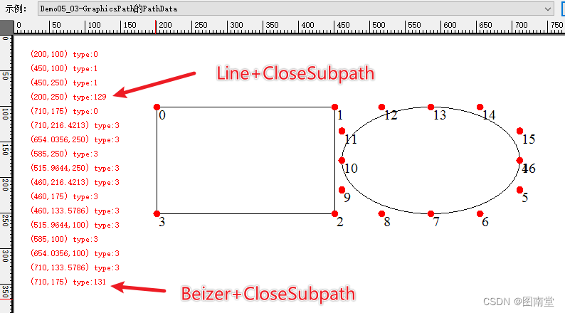
public System.Drawing.Drawing2D.PathData PathData { get; }
获取该路径的点(Points)与类型(Types)数组。
var rect1 = new Rectangle(200, 100, 250, 150);
var rect2 = new Rectangle(460, 100, 250, 150);
using (var graphicsPath = new GraphicsPath())
{graphicsPath.AddRectangle(rect1);graphicsPath.AddEllipse(rect2);e.Graphics.DrawPath(Pens.Black, graphicsPath);var pathData = graphicsPath.PathData;var pts = pathData.Points;var types = pathData.Types;int offset = 20;using (var font = new Font("Times New Roman", 15)){for (int i = 0; i < pathData.Points.Length; i++){var pt = pts[i];e.Graphics.FillEllipse(Brushes.Red, pt.X - 5, pt.Y - 5, 10, 10);e.Graphics.DrawString(i.ToString(), font, Brushes.Black, pt);DrawString(e, $"({pt.X},{pt.Y}) type:{types[i]}", ref offset);}}
}
PathPoints、PathTypes
等价于PathData的Points和Types
PointCount
原型:
public int PointCount { get; }
获取路径点集或类型的个数。
方法
AddArc添加椭圆弧
原型:
public void AddArc (float x, float y, float width, float height, float startAngle, float sweepAngle);
public void AddArc (int x, int y, int width, int height, float startAngle, float sweepAngle);
public void AddArc (System.Drawing.Rectangle rect, float startAngle, float sweepAngle);
public void AddArc (System.Drawing.RectangleF rect, float startAngle, float sweepAngle);
通过定义一个矩形来确定椭圆,再通过起始角度(x轴顺时针开始)和经过的角度,来确定一条椭圆弧线。
var rect = new Rectangle(200, 100, 300, 200);
using (var graphicsPath = new GraphicsPath())
{//从x轴顺时针30度开始,共画180度的弧graphicsPath.AddArc(rect, 30, 180);e.Graphics.DrawPath(Pens.Red, graphicsPath);graphicsPath.Reset();//从210度开始,共画180度的弧graphicsPath.AddArc(rect.Left, rect.Top, rect.Width, rect.Height, 30 + 180, 180);e.Graphics.DrawPath(Pens.LightGreen, graphicsPath);e.Graphics.DrawRectangle(Pens.Black, rect);e.Graphics.FillEllipse(Brushes.Red, (rect.Left + rect.Right) / 2f - 3, (rect.Top + rect.Bottom) / 2f - 3, 6, 6);
}
画一条红色的椭圆弧从30°到210°,再画一条亮绿的椭圆弧从210°到30°,刚好形成一个椭圆。

AddBezier添加贝赛尔曲线
原型:
public void AddBezier (System.Drawing.Point pt1, System.Drawing.Point pt2, System.Drawing.Point pt3, System.Drawing.Point pt4);
public void AddBezier (System.Drawing.PointF pt1, System.Drawing.PointF pt2, System.Drawing.PointF pt3, System.Drawing.PointF pt4);
public void AddBezier (int x1, int y1, int x2, int y2, int x3, int y3, int x4, int y4);
public void AddBezier (float x1, float y1, float x2, float y2, float x3, float y3, float x4, float y4);
通过添加4个点(1个起始点,2个控制点,1个终止点)来生成一条三次贝赛尔曲线。
// 定义贝塞尔曲线的四个控制点
Point[] bezierPoints = new Point[]
{new Point(50, 200),    // 起点new Point(150, 50),    // 控制点1new Point(250, 350),   // 控制点2new Point(350, 200)    // 终点
};
using (var path = new GraphicsPath())
{//绘制三次贝赛尔曲线path.AddBezier(bezierPoints[0], bezierPoints[1], bezierPoints[2], bezierPoints[3]);e.Graphics.DrawPath(Pens.LightGreen, path);//绘制四个点foreach (var pt in bezierPoints){e.Graphics.FillEllipse(Brushes.Red, pt.X - 3, pt.Y - 3, 6, 6);}e.Graphics.DrawLine(Pens.Red, bezierPoints[0], bezierPoints[1]);e.Graphics.DrawLine(Pens.Red, bezierPoints[2], bezierPoints[3]);
}
定义四个点,生成一条贝赛尔曲线

AddClosedCurve添加封闭基数样条曲线
原型:
public void AddClosedCurve (params System.Drawing.Point[] points);//默认tension=0.5f
public void AddClosedCurve (params System.Drawing.PointF[] points);//默认tension=0.5f
public void AddClosedCurve (System.Drawing.Point[] points, float tension);
public void AddClosedCurve (System.Drawing.PointF[] points, float tension);
添加经过给定点集的基数样条曲线,可通过tension控制曲线的弯曲程度(0至1之间,0最尖锐,1最平滑)
// 定义贝四个点
Point[] pts = new Point[]
{new Point(50, 200),    new Point(150, 50),    new Point(250, 350),   new Point(350, 200)
};
using (var path = new GraphicsPath())
{path.AddClosedCurve(pts);e.Graphics.DrawPath(Pens.LightGreen, path);path.Reset();path.AddClosedCurve(pts,0.25f);e.Graphics.DrawPath(Pens.Red, path);path.Reset();path.AddClosedCurve(pts, 0.75f);e.Graphics.DrawPath(Pens.Black, path);//绘制四个点foreach (var pt in pts){e.Graphics.FillEllipse(Brushes.Red, pt.X - 3, pt.Y - 3, 6, 6);}
}
给定4个点(与前面贝赛尔曲线相同的四个点),生成不同tension的基数样条曲线。

AddCurve添加基数样条曲线(开放)
原型:
public void AddCurve (System.Drawing.PointF[] points, int offset, int numberOfSegments, float tension);
public void AddCurve (System.Drawing.Point[] points, int offset, int numberOfSegments, float tension);
public void AddCurve (System.Drawing.PointF[] points, float tension);
public void AddCurve (params System.Drawing.Point[] points);//默认tension=0.5
public void AddCurve (params System.Drawing.PointF[] points);//默认tension=0.5
public void AddCurve (System.Drawing.Point[] points, float tension);
| 参数 | 说明 |
|---|---|
| points | 待绘制基数样条要经过的点 |
| offset | 从第几个点开始画曲线(序号为0开始) |
| numberOfSegments | 要画几段(两个点之间为1段)曲线 offset+numberOfSegments<=points的个数-1 |
| tension | 张力系数,指定曲线在控制点之间弯曲量的值,在0到1之间。 大于 1 的值会产生不可预测的结果。 |
两个基数样条控制点之间的曲线,其它也是一段贝赛尔曲线。
具体算法见下面示例。
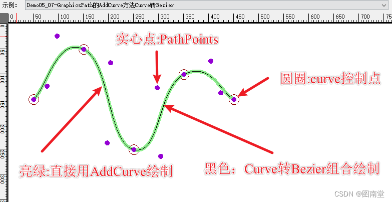
通过AddCurve和DrawBezier绘制相同的基数样条曲线。
[System.ComponentModel.Description("GraphicsPath的AddCurve方法Curve转Bezier")]
public void Demo05_07(PaintEventArgs e)
{Point[] controlPoints = {new Point(50, 150), // 控制点1new Point(150, 50), // 控制点2new Point(250, 250), // 控制点3new Point(350, 100),  // 控制点4new Point(450, 150)  // 控制点5};//绘制基数样条曲线的控制点foreach (var pt in controlPoints){e.Graphics.DrawEllipse(Pens.DarkRed, pt.X - 10, pt.Y - 10, 20, 20);}using (var path=new GraphicsPath()){float tension = 0.8f;path.AddCurve(controlPoints, tension);// 绘制基数样条曲线e.Graphics.DrawPath(new Pen(Color.LightGreen, 7), path);// 将基数样条曲线转换为贝赛尔曲线后再绘制for (int i = 0; i < controlPoints.Length - 1; i++){PointF[] bezierPoints = CurveToBezier(i > 0 ? controlPoints[i - 1] : controlPoints[i],controlPoints[i],controlPoints[i + 1],i < controlPoints.Length - 2 ? controlPoints[i + 2] : controlPoints[i + 1],tension);//curve转beziere.Graphics.DrawBezier(Pens.Black, bezierPoints[0], bezierPoints[1], bezierPoints[2], bezierPoints[3]);}//绘制路径所有控制点var dataPoints = path.PathPoints;foreach(var pt in dataPoints){e.Graphics.FillEllipse(Brushes.DarkViolet, pt.X - 5, pt.Y - 5, 10, 10);}}
}
/// <summary>
/// 将四个基数样条控制点转换为贝塞尔曲线控制点
/// </summary>
/// <param name="p0"></param>
/// <param name="p1"></param>
/// <param name="p2"></param>
/// <param name="p3"></param>
/// <param name="tension">张力系数(0~1)之间</param>
/// <returns></returns>
private PointF[] CurveToBezier(PointF p0, PointF p1, PointF p2, PointF p3, float tension = 0.5f)
{float t = tension / 3;return new PointF[]{p1,new PointF(p1.X + t * (p2.X - p0.X), p1.Y + t * (p2.Y - p0.Y)),new PointF(p2.X - t * (p3.X - p1.X), p2.Y - t * (p3.Y - p1.Y)),p2};
}
一样定义多个控制点,分多次绘制基数样条曲线
Pen penRed = new Pen(Color.Red, 3);
Pen penLightGreen = new Pen(Color.Green, 1);[System.ComponentModel.Description("GraphicsPath的AddCurve方法分段绘制")]
public void Demo05_08(PaintEventArgs e)
{Point[] controlPoints = {new Point(50, 150), // 控制点1new Point(150, 50), // 控制点2new Point(250, 250), // 控制点3new Point(350, 100),  // 控制点4new Point(450, 150)  // 控制点5};//绘制基数样条曲线的控制点foreach (var pt in controlPoints){e.Graphics.DrawEllipse(Pens.DarkRed, pt.X - 10, pt.Y - 10, 20, 20);}using (var path = new GraphicsPath()){float tension = 0.8f;//从第1个点开始,绘制3段基数样条曲线path.AddCurve(controlPoints,0,3,tension);e.Graphics.DrawPath(penRed, path);path.Reset();//从第2个点开始,绘制3段基数样条曲线path.AddCurve(controlPoints, 1, 3, tension);e.Graphics.DrawPath(penLightGreen, path);}
}

AddEllipse添加椭圆
原型:
public void AddEllipse (System.Drawing.Rectangle rect);
public void AddEllipse (System.Drawing.RectangleF rect);
public void AddEllipse (int x, int y, int width, int height);
public void AddEllipse (float x, float y, float width, float height);
通过定义矩形来确定一个椭圆路径
var rect = new RectangleF(100, 100, 200, 150);using (var path = new GraphicsPath())
{//添加椭圆路径path.AddEllipse(rect);e.Graphics.DrawPath(penRed, path);e.Graphics.DrawRectangle(penLightGreen,rect.X, rect.Y, rect.Width, rect.Height);
}
绘制一个矩形包着的椭圆

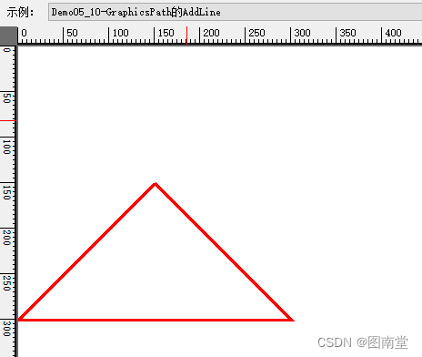
AddLine添加线段
原型:
public void AddLine (int x1, int y1, int x2, int y2);
public void AddLine (float x1, float y1, float x2, float y2);
public void AddLine (System.Drawing.Point pt1, System.Drawing.Point pt2);
public void AddLine (System.Drawing.PointF pt1, System.Drawing.PointF pt2);
通过定义两个点的坐标,添加一条线段。
using (var path = new GraphicsPath())
{path.AddLine(150, 150, 300, 300);path.AddLine(300, 300, 0, 300);path.AddLine(0, 300, 150, 150);e.Graphics.DrawPath(penRed, path);
}
添加三条线段围成一个三角形
内容太多,另起一篇吧!
【学习笔记】Windows GDI绘图目录