OGL(教程40)——Stencil Shadow Volume
http://ogldev.atspace.co.uk/www/tutorial40/tutorial40.html
参考网址:
https://developer.download.nvidia.cn/books/HTML/gpugems/gpugems_ch09.html
https://www.nvidia.com/docs/IO/8230/GDC2003_ShadowVolumes.pdf
https://www.gamedev.net/articles/programming/graphics/the-theory-of-stencil-shadow-volumes-r1873/
https://www.joshbeam.com/articles/stenciled_shadow_volumes_in_opengl/
http://nuclear.mutantstargoat.com/articles/volume_shadows_tutorial_nuclear.pdf
https://www.gamasutra.com/view/feature/131351/the_mechanics_of_robust_stencil_.php?page=1
in tutorials 23 & 24 we studies the shadow map technique which is a relatively simple way to get shadows into your 3D world. shadow maps are in a disadvantage when trying to generate a shadow for a point light source. u need a direction vector in order to generate the shadow map and since a point light casts its light all over the place, it is difficult to get such a vector.
while there are methods to overcome this, they are a bit complex and make the shadow map technique more suitable for spot lights. the stencil shadow volume is an interesting technique that provides a straightforward solution to the problem of point lights.
this technique was discovered by william biloeau and michael songy in 1998 and was popularized by john carmarck in his doom3 engine (2002).
if u have followed the tutorials thus far, u have actually seen a variation of this technique in our mini series of tutorials on deferred shading. with deferred shading we needed a way to block the light influence and we have used a light volume for that purpose.
we processed lighting only on stuff within the light volume. now we are going to do the opposite. we will create a shadow volume and process lighting only on stuff outside of it. same as in light volume we will use the stencil buffer as a key component of the algorithm. hence the name – stencil shadow volume.
the idea behind the shadow volume algorithm is to extend the sihouette 轮廓 of an object which is created when light falls upon it into a volume and then render that volume into the stencil buffer using a couple of simple stencil operations. the key idea is that when an object is inside the volume (and therefore in shadow) the front polygons of the volume win the depth test against the polygons of the object and the back polygons of the volume fail the same test.
we are going to setup the stencil operation according to a method known as depth fail. people often start the description of the shadow volume technique using a more straightforward (原文中这个字母打错了,少了t)method called depth pass, that method has a known problem when the viewer itself is inside the shadow volume and depth fail fixes that problem. therefore, i have skipped depth pass altogether and went directly to depth fail. take a look at the following picture:
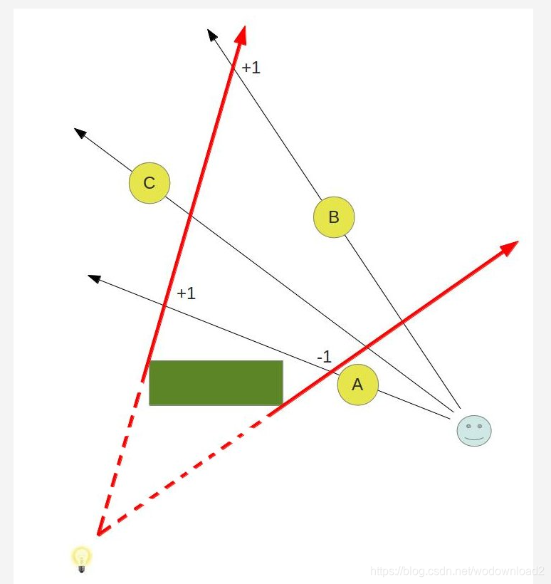
你可能不知道上面的图的意思了吧,我来解释下,本文采用的是深度测试失败的方法,而深度测试的还是针对摄像机的,比如上面的小人头像。这个就是摄像机。
有两个法则:
1、渲染阴影体的前面的时候,当深度测试失败的时候,则减去1;
2、渲染阴影体的背面的时候,当深度测试失败的时候,则加上1;
最后模板值不为0的,则表明是在阴影体里面;
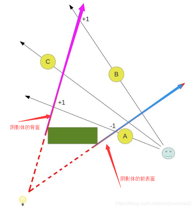
比如上面的蓝色箭头,就代表了阴影体的前表面;而粉色的箭头代表了阴影体的背面。
当渲染蓝色前表面的时候,进行深度测试,A物体的深度小于蓝色前表明,深度测试失败;什么是失败了,谁失败了,答案是前表面失败了,因为此时我们是将前表面的深度和A物体的深度进行比较,前表面的深度大于A物体,所以根据深度测试的比较公式,要小于等于才能测试成功,所以前表面神的测试失败,故,根据原则1,其模板值要减去1;
同理,当渲染粉色箭头的时候,其深度要比A的深度,也是大于,所以同样失败,根据原则2,其模板值要加上1;
此时对于A物体来说,经历了-1,+1的操作,最终模板值为0,而不为0,则表明此物体不在阴影里。
我们此时再来看看物体B:
对于前表面,蓝色箭头,蓝色箭头的深度要小于B物体,深度测试居然成功了,那么深度测试成功的情况下,对模板值是不做任何修改的。
对于后表面,粉色箭头,粉色箭头的深度要大于B物体,深度测试失败了,此时根据原则2,背面深度测试失败,其模板值要加上1。
最终B物体的模板值为1;根据结论知道,深度值不为0的在阴影体里面。
我们再来看看物体C:
前表面和后表面的深度都小于C物体,所以模板值不做任何变化。故最终C的模板值为0,而为0表面不在阴影里。
we have a light bulb灯泡,at the bottom left corner and a green object (called an occluder) which casts shadow due to that light. 绿色块挡住了光,释放阴影。three round objects are rendered in this scene as well. object b is shadowed while A and C are not.

the red arrows bound the area of the shadow volume (the dashed part of the line is not part of it).
let us see how we can utilize the stencil buffer to get shadows working here. we start by rendering the actual objects (A,B,C and the green box) into the depth buffer. when we are done we have the depth of the closest pixels available to us.
then we go over the objects in the scene one by one and create a shadow volume for each one. the example here shows only the shadow volume of the green box but in a complete application we would also create volumes for the round objects because they cast shadows of their own. 这段话的意思是,我们上图的只是给绿色的立方体创建了阴影体积,而整个程序会对ABC三个圆的物体都创建阴影体积。
the shadow volume is created by detecting its silhouette (make sure u fully understand tutorial 39 before starting this one) and extending it into infinity. we render that volume into the stencil buffer using the following simple rules:
1/ if the depth test fails when rendering the back facing polygons of the shadow volume we increment the value in the stencil buffer.
2/ if the depth test fails when rendering the front facing polygons of the shadow volume we decrement the value in the stencil buffer.
3/ we do nothing in the following cases: depth test pass, stencil test fails.
let us see what happens to the stencil buffer using the above scheme. the front and back facing triangles of the volume that are covered by object A fail the depth test. we increment and decrement the values of the pixels covered by object A in the stencil buffer which means they are left at zero. in the case of object B the front facing triangles of the volume win the depth test while the back facing ones fails. therefore, we only increment the stencil value. the volume triangles (front and back facing) that covering object C win the depth test. therefore, the stencil value is not updated and remains at zero.
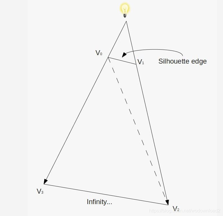
let us see how to put that knowledge into practice. as we said earlier, we need to render a volume which is created when we extend the silhouette of an occluder. we can start with the code from the previous tutorial which detects the silhouette. all we need to do is to extend the silouette edges into a volume. this is done by emitting a quad ( or actually, four vertices in triangle strip topology) from the GS for each silhouette edge. the first two vertices come from the silhouette edge and the other two vertices are generated when we extend the edge vertices into infinity along the vector from the light position to the vertices. by extending into inifinity we make sure the volume captures everything which lies in the path of the shadow. this quad is depicted in the following picture:
when we repeat this process of emitting quads from all silhouette edges a volume is created. is that enough?? definitely not. the problem is that this volume looks kind of like a truncated cone without its caps. since our algorithm depends on checking the depth test of the front and back triangles of the volume we might end up with a case where the vector from the eye to the pixel goes through only either the front or back of the volume:
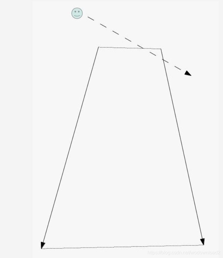
the solution to this problem is to generate a volume which is closed on both sides. this is done by creating a front and a back cap to the volume (the dotted lines in the picture above). creating the front cap is very easy. every triangle which faces the light becomes part of the front cap. while this may not be the most efficient solution and u could probably create a front cap using fewer triangles it is definitely the simplest solution. the back cap is almost as simple. we just need to extend the vertices of light facing triangle to infinity ( along the vector from the light to each vertex) and reverse their order (else the resulting triangle will point inside the volume).
这段主要阐述了,如何为何要有顶和底,因为我们依赖的是深度测试算法,必须知道一个像素是在阴影体的前面还是背面,所以必须阴影体必须是一个封闭体。
这里顶可以遍历每个轮廓边形成四边形的上边;而两条斜边,即是上轮廓边沿着光源的方向的延伸;
底边呢?是无限远处的两个点,这里在只要使用齐次坐标的w=0即可,表示无限远处的点了;
这样就得到四个点,构成一个四边形;
最后将底边的三角形进行顺序的反转,以让底边的法线是朝着外表面的。
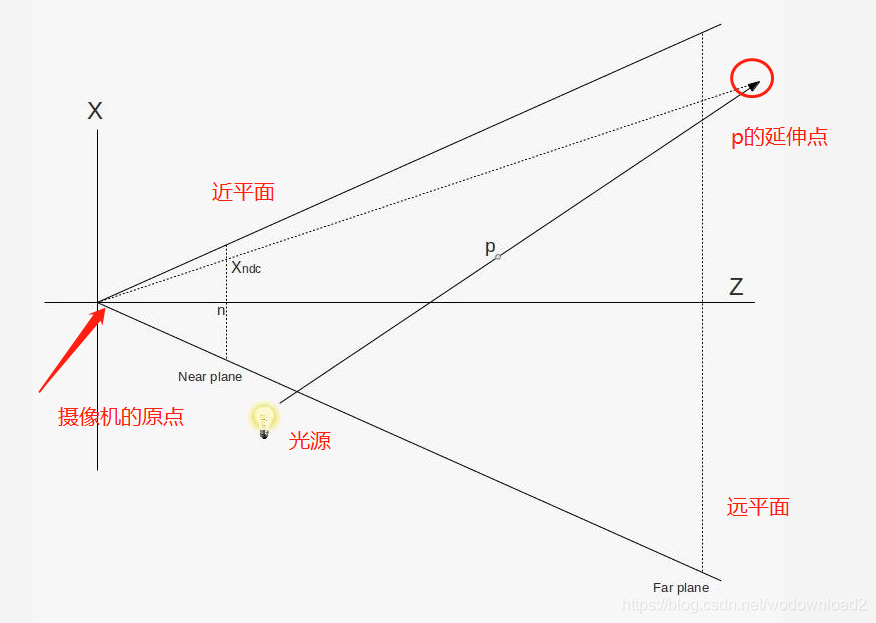
the world ‘infinity’ has been mentioned here a few times and we now need to define exactly what this means. take a look at the following picture:
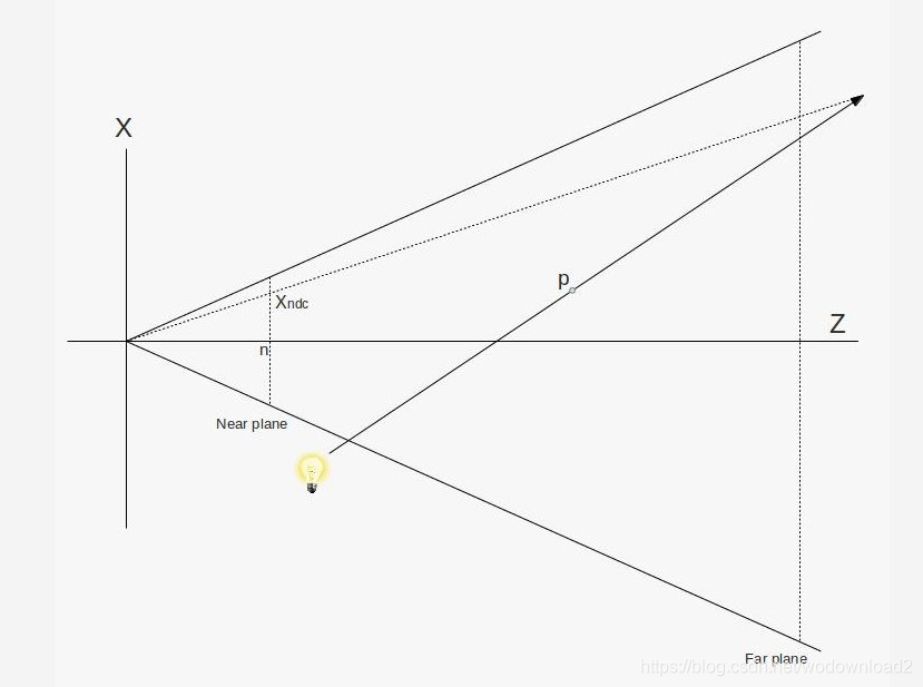
what we see is a picture of the frustum taken from above. the light bulb emits a ray which goes through point ‘p’ and continues to infinity. in other words, ‘p’ is extended to infinity. obviously, at infinity the position of point p is simply (infinity, infinity, infinity), but we do not care about that. we need to find a way to rasterize the triangles of the shadow volume which means we must project its vertices on the projection plane. this projection plane is in fact the near plane. while ‘p’ is extended to infinity along the light vector we can still project it back on the near plane. this is done by the dotted line that that goes from the origin and crosses the light vector somewhere. we want to find ‘Xp’ which is the X value of the point where that vector crosses the near plane.
let us descibe any point on the light vector as ‘p+vt’ where ‘v’ is the vector from the light source to point ‘p’ and ‘t’ is a scalar which goes from 0 towards infinity. from the above picture and due triangle similarities we can say that: 相似三角形
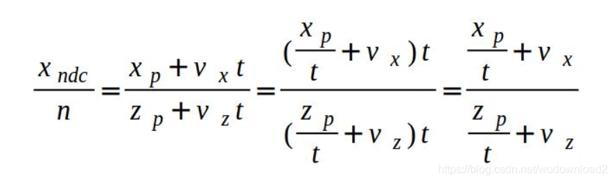
where ‘n’ is the Z value of the near plane. as ‘t’ goes to infinity we are left with:

so this is how we find the projection of ‘p’ at infinity on the near plane. now here is a bit of magic-- turns out that to calcualte Xp and Yp accordingly to the above we just need to multiply the vector (Vx,Vy,Vz,0) (where ‘V’ is the vector from the light source to point ‘p’) by the view/projection matrix and apply perspecive divide on it. we are not going to prove it here but u can try this yourself and see the result. so the bottom line is that whenever we need to rasterize a triangle that contains a vertex which was extended to infinity along some vector we simply multiply that vector by the view/projection matrix while adding a ‘w’ component with the value of zero to it. we will use that technique extensively in the GS below.
glutInitDisplayMode(GLUT_DOUBLE|GLUT_RGBA|GLUT_DEPTH|GLUT_STENCIL);
before u start working on this tutorial make sure u initialize FreeGLUT per the code in bold face above. without it the framebuffer will be created without a stencil buffer and nothing will work.
virtual void RenderSceneCB()
{
    CalcFPS();

    m_scale += 0.1f;

    m_pGameCamera->OnRender();

    glDepthMask(GL_TRUE);

    glClear(GL_COLOR_BUFFER_BIT | GL_DEPTH_BUFFER_BIT | GL_STENCIL_BUFFER_BIT);

    RenderSceneIntoDepth();

    glEnable(GL_STENCIL_TEST);

    RenderShadowVolIntoStencil();

    RenderShadowedScene();

    glDisable(GL_STENCIL_TEST);

    RenderAmbientLight();

    RenderFPS();

    glutSwapBuffers();
}
the main render loop function executes the three stages of the algorithm. first we render the entire scene into the depth buffer (without touching the color buffer). then we render the shadow volume into the stencil buffer while setting up the stencil test as described in the background session. and finally the scene itself is rendered while taking into account the values in the stencil buffer. (i.e. only those pixels whose stencil value is zero are rendered).
1/RenderSceneInfoDepth();
我们首先做的是渲染整个场景到深度缓存,而不进行颜色缓冲的写入。这样就得到了所有物体的深度值了。
2/RenderShadowVolIntoStencil();
接着我们做的是进行模板缓冲的写入,使用的规则是上面的两条规则。
3/RenderShadowedScene();
最后是根据模板缓冲的值再次进行渲染场景。
an important difference between this method and shadow map is that shadowed pixels in the stencil shadow volume method never reach the fragment shader. when we were uisng shadow map we had the opportunity to calculate ambient lighting on shadowed pixels. we do not have that opportunity here. therefore, we add an ambient pass outside the stencil test.
这个方法的与使用阴影映射最大的不同在于,在阴影体里面的像素是不会走到片段着色器的。而在shadow map的方法中,在阴影里面的像素还是有机会进行环境光的计算的。针对这个情况,为了防止阴影里面的像素过度黑暗,我们在模板测试的外边加了一个环境光的通道。稍微给他加点颜色。
note that we enable writing to the depth buffer before the call to glClear. without it the depth buffer will not be cleared.
第一步:将得到场景物体的深度信息
我们把摄像机放在了眼睛的位置;
设置好透视投影矩阵;
设置好立方体模型的旋转、缩放、以及WVP矩阵、最后调用m_box.Render()方法;
void RenderSceneIntoDepth()
{
    glDrawBuffer(GL_NONE);

    m_nullTech.Enable();

    Pipeline p;

    p.SetCamera(m_pGameCamera->GetPos(), m_pGameCamera->GetTarget(), m_pGameCamera->GetUp());
    p.SetPerspectiveProj(m_persProjInfo);

    m_boxOrientation.m_rotation = Vector3f(0, m_scale, 0);
    p.Orient(m_boxOrientation);
    m_nullTech.SetWVP(p.GetWVPTrans());
    m_box.Render();

    p.Orient(m_quadOrientation);
    m_nullTech.SetWVP(p.GetWVPTrans());
    m_quad.Render();
}
here we render the entire scene into the depth buffer, while disabling writes to the color buffer. we have to do this because in the next step we render the shadow volume and we need the depth fail algorithm to be performed correctly. if the depth buffer is only partially updated we will get incorrect results.
第二步:得到模板信息
设置了两个模板测试的规则:
glStencilOpSeparate(GL_BACK, GL_KEEP, GL_INCR_WRAP, GL_KEEP);
glStencilOpSeparate(GL_FRONT, GL_KEEP, GL_DECR_WRAP, GL_KEEP);
void RenderShadowVolIntoStencil()
{
    glDepthMask(GL_FALSE);
    glEnable(GL_DEPTH_CLAMP);
    glDisable(GL_CULL_FACE);

    // We need the stencil test to be enabled but we want it
    // to succeed always. Only the depth test matters.
    glStencilFunc(GL_ALWAYS, 0, 0xff);

    // Set the stencil test per the depth fail algorithm
    glStencilOpSeparate(GL_BACK, GL_KEEP, GL_INCR_WRAP, GL_KEEP);
    glStencilOpSeparate(GL_FRONT, GL_KEEP, GL_DECR_WRAP, GL_KEEP);

    m_ShadowVolTech.Enable();

    m_ShadowVolTech.SetLightPos(m_pointLight.Position);

    // Render the occluder
    Pipeline p;
    p.SetCamera(m_pGameCamera->GetPos(), m_pGameCamera->GetTarget(), m_pGameCamera->GetUp());
    p.SetPerspectiveProj(m_persProjInfo);
    m_boxOrientation.m_rotation = Vector3f(0, m_scale, 0);
    p.Orient(m_boxOrientation);
    m_ShadowVolTech.SetVP(p.GetVPTrans());
    m_ShadowVolTech.SetWorldMatrix(p.GetWorldTrans());
    m_box.Render();

    // Restore local stuff
    glDisable(GL_DEPTH_CLAMP);
    glEnable(GL_CULL_FACE);
}
this is where things become interesting. we use a special technique which is based on the silhouette technique from the previous tutorial. it generates the volume (and its caps) from the silhouette of the occluder.
first we disable writes to the depth buffer (writes to the color are already disabled from the previous step).
we are only going to update the stencil buffer. we enable depth clamp which will cause our projected-to-infinity-vertices (from the far cap) to be clamped to the maximum depth value. otherwise, the far cap will simply be clipped away.
we also disable back face culling because our algorithm depends on rendering all the triangles of the volume.
then we set the stencil test (which has been enabled in the main render function) to always succeed and we set the stencil operations for the front and back faces according to the depth fail algorithm. 我们让模板测试一直通过,只是对前、后表面进行上述两个规则的测试判断。after that we simply set everything the shader needs and render the occluder.
第三步:渲染有阴影的场景
void RenderShadowedScene()
{
    glDrawBuffer(GL_BACK);

     // Draw only if the corresponding stencil value is zero
    glStencilFunc(GL_EQUAL, 0x0, 0xFF);

    // prevent update to the stencil buffer
    glStencilOpSeparate(GL_BACK, GL_KEEP, GL_KEEP, GL_KEEP);

    m_LightingTech.Enable();

    m_pointLight.AmbientIntensity = 0.0f;
    m_pointLight.DiffuseIntensity = 0.8f;

    m_LightingTech.SetPointLights(1, &m_pointLight);

    Pipeline p;
    p.SetPerspectiveProj(m_persProjInfo);
    p.SetCamera(m_pGameCamera->GetPos(), m_pGameCamera->GetTarget(), m_pGameCamera->GetUp());

    m_boxOrientation.m_rotation = Vector3f(0, m_scale, 0);
    p.Orient(m_boxOrientation);
    m_LightingTech.SetWVP(p.GetWVPTrans());
    m_LightingTech.SetWorldMatrix(p.GetWorldTrans());
    m_box.Render();

    p.Orient(m_quadOrientation);
    m_LightingTech.SetWVP(p.GetWVPTrans());
    m_LightingTech.SetWorldMatrix(p.GetWorldTrans());
    m_pGroundTex->Bind(COLOR_TEXTURE_UNIT);
    m_quad.Render();
}
只渲染那些stencil buffer=0的像素
we can now put the updated stencil buffer into use. based on our algorithm we set rendering to succeed only when the stencil value of the pixel is ecactly zero.
in addition, we also prevent updates to the stencil buffer by setting the stencil test action to GL_KEEP.
and that is it!!! 到此为止。。。
we can now use the standard lighting shader to render the scene. just remember to enable writing into the color buffer before you start…
void RenderAmbientLight()
{
    glEnable(GL_BLEND);
    glBlendEquation(GL_FUNC_ADD);
    glBlendFunc(GL_ONE, GL_ONE);

    m_LightingTech.Enable();

    m_pointLight.AmbientIntensity = 0.2f;
    m_pointLight.DiffuseIntensity = 0.0f;

    m_LightingTech.SetPointLights(1, &m_pointLight);

    m_pGroundTex->Bind(GL_TEXTURE0);

    Pipeline p;
    p.SetPerspectiveProj(m_persProjInfo);
    p.SetCamera(m_pGameCamera->GetPos(), m_pGameCamera->GetTarget(), m_pGameCamera->GetUp());

    m_boxOrientation.m_rotation = Vector3f(0, m_scale, 0);
    p.Orient(m_boxOrientation);
    m_LightingTech.SetWVP(p.GetWVPTrans());
    m_LightingTech.SetWorldMatrix(p.GetWorldTrans());
    m_box.Render();

    p.Orient(m_quadOrientation);
    m_LightingTech.SetWVP(p.GetWVPTrans());
    m_LightingTech.SetWorldMatrix(p.GetWorldTrans());
    m_pGroundTex->Bind(COLOR_TEXTURE_UNIT);
    m_quad.Render();

    glDisable(GL_BLEND);
}
the ambient pass help us avoid completely black pixels that were dropped by the stencil test. in real life we usually do not see such extreme shadows so we add a bit of ambient light to all pixels.
this is done by simply doing anotherr lighting pass outside the boudraries of the stencil test.
couple of things to note here:
we zero out the diffuse intensity ( because that one is affected by the shadow)
and we enable blending (to merge the results of the previous pass with this one).
now let us take a look at the shaders of the volume technique.
#version 330

layout (location = 0) in vec3 Position;
layout (location = 1) in vec2 TexCoord;
layout (location = 2) in vec3 Normal;

out vec3 PosL;

void main()
{
    PosL = Position;
}
in the VS we simply forward the position as-is (in local space). the entire algorithm is implemented in the GS.
#version 330
layout (triangles_adjacency) in; // six vertices in
layout (triangle_strip, max_vertices = 18) out;
in vec3 PosL[]; // an array of 6 vertices (triangle with adjacency)
uniform vec3 gLightPos;
uniform mat4 gWVP;
float EPSILON = 0.0001;
// Emit a quad using a triangle strip
void EmitQuad(vec3 StartVertex, vec3 EndVertex)
{
// Vertex #1: the starting vertex (just a tiny bit below the original edge)
vec3 LightDir = normalize(StartVertex - gLightPos);
gl_Position = gWVP * vec4((StartVertex + LightDir * EPSILON), 1.0);
EmitVertex();
// Vertex #2: the starting vertex projected to infinity
gl_Position = gWVP * vec4(LightDir, 0.0);
EmitVertex();
// Vertex #3: the ending vertex (just a tiny bit below the original edge)
LightDir = normalize(EndVertex - gLightPos);
gl_Position = gWVP * vec4((EndVertex + LightDir * EPSILON), 1.0);
EmitVertex();
// Vertex #4: the ending vertex projected to infinity
gl_Position = gWVP * vec4(LightDir , 0.0);
EmitVertex();
EndPrimitive();
}
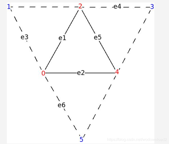
void main()
{
vec3 e1 = WorldPos[2] - WorldPos[0];
vec3 e2 = WorldPos[4] - WorldPos[0];
vec3 e3 = WorldPos[1] - WorldPos[0];
vec3 e4 = WorldPos[3] - WorldPos[2];
vec3 e5 = WorldPos[4] - WorldPos[2];
vec3 e6 = WorldPos[5] - WorldPos[0];
vec3 Normal = cross(e1,e2);
vec3 LightDir = gLightPos - WorldPos[0];
// Handle only light facing triangles
if (dot(Normal, LightDir) > 0) {
Normal = cross(e3,e1);
if (dot(Normal, LightDir) <= 0) {
vec3 StartVertex = WorldPos[0];
vec3 EndVertex = WorldPos[2];
EmitQuad(StartVertex, EndVertex);
}
Normal = cross(e4,e5);
LightDir = gLightPos - WorldPos[2];
if (dot(Normal, LightDir) <= 0) {
vec3 StartVertex = WorldPos[2];
vec3 EndVertex = WorldPos[4];
EmitQuad(StartVertex, EndVertex);
}
Normal = cross(e2,e6);
LightDir = gLightPos - WorldPos[4];
if (dot(Normal, LightDir) <= 0) {
vec3 StartVertex = WorldPos[4];
vec3 EndVertex = WorldPos[0];
EmitQuad(StartVertex, EndVertex);
}
// render the front cap
LightDir = (normalize(PosL[0] - gLightPos));
gl_Position = gWVP * vec4((PosL[0] + LightDir * EPSILON), 1.0);
EmitVertex();
LightDir = (normalize(PosL[2] - gLightPos));
gl_Position = gWVP * vec4((PosL[2] + LightDir * EPSILON), 1.0);
EmitVertex();
LightDir = (normalize(PosL[4] - gLightPos));
gl_Position = gWVP * vec4((PosL[4] + LightDir * EPSILON), 1.0);
EmitVertex();
EndPrimitive();
// render the back cap
LightDir = PosL[0] - gLightPos;
gl_Position = gWVP * vec4(LightDir, 0.0);
EmitVertex();
LightDir = PosL[4] - gLightPos;
gl_Position = gWVP * vec4(LightDir, 0.0);
EmitVertex();
LightDir = PosL[2] - gLightPos;
gl_Position = gWVP * vec4(LightDir, 0.0);
EmitVertex();
}
}
the GS starts in pretty much the same way as the sihouette shader in the sense that we only crare about triangles that are light facing.
when we detect a silhouette edge we extend a quad from it towards infinity (see below).
remember that the indices of the vertices of the original triangles are 0,2 and 4 and the adjacenct vertices are 1,3,5 (see picture in the previous tutorial).
after we take care of the quads we emit the front and back caps.
note that for the front cap we do not use the original triangle as-is.
instead, we move it along the light vector by a very small amount (we do it by normalizing the light vector and multiplying it by a small epsilon). the reason is that due to floating point errors we might encouter bizarre corruptions where the volume hides the front cap. moving the cap away from the volume by just a bit works around this problem.
for the back cap we simply project the original vertices into infinity along the light vector and emit them in reverse order.
in order to emit a quad from an edge we project both vertices to infinity along the light direction and generate a triangle strip.
note that the original vertices are moved along the light vector by a very small amount, to match the front cap.
it is critical that we set the maximum output vertices from the GS coorectly (see ‘max_vertices’ above). we have 3 vertices for the front cap, 3 for the back cap and 4 for each silhouette edge.
when i was working on this tutorial i accidently set this value to 10 and got very strange coorruptions. make sure u do not make the same misktake…